Helpful Hints for SA Users, May 2012
 Looking to save time and be more productive? Below are a few functional commands in SpatialAnalyzer® (SA) that are extremely helpful, but often overlooked.
 Helpful Hints for SA Users, May 2012
-
1. Do you have a job that has all the measurements sitting in one single group, but it would make your life easier to separate the points into different groups for reporting and analysis? You could use group manager, but what if the points are not taken in a particular order and the point names are arbitrarily named?
There is an SA function that will help you quickly grab measured points from the graphical window and place them a new group. Look at Construct – Points – From Existing Points – Move. This operation will retain the relationship of the measured point to the instrument(s) that took it. To use the operation, select your points, put the name of the new group in the input dialog box, and press Enter. Your points will now reside in their own point group. Be aware; however, that the point names will change. The new point name will have the name of the original point group as a prefix to the original point name.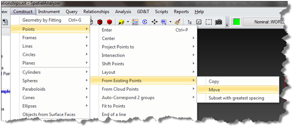
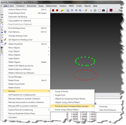
If needed, you can quickly and easily rename the points using several methods in SA found under the Edit menu. If you have nominal points that you need to associate the measurement with, use Edit - Rename –Points by Auto-Corresponding 2 groups – Proximity , or Inter Point Distance. If you do not, but want a shorter name, use Edit - Rename – Points using a Name Pattern. This method provides a means to enter a prefix and/or suffix to a numerical counter value, providing an easy path to changing the naming scheme for groups of points.
-
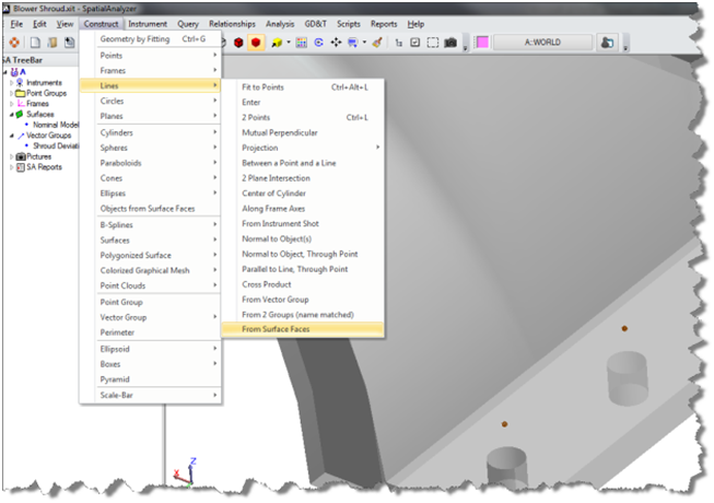
2. Do you have a CAD model that you’ve imported and you want to create centerlines for a hole or group of holes? Try using Construct-Line-From Surface Faces. This operation prompts you to pick the inside wall of each hole that you would like to create a centerline. Once you’ve selected all the holes you need, simply press Enter, and you will get a centerline.
-
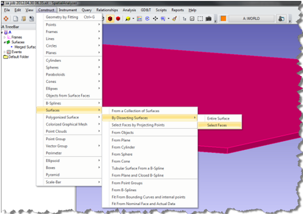
3. Do you need to inspect a long, thin part that you suspect is warped? Usually, if you have CAD that you’ve imported and will be inspecting to, you will see the part come into SA as a solid (one surface, many faces).
You may want to extract the faces of interest from the solid to ensure that your analysis will always be performed to the intended side of the part. If you aren’t careful, you could be analyzing a measurement of an outside surface of a part to the inside surface of the model. To extract a face from a solid model, use Construct-Surfaces-By Dissecting Surfaces-Select Faces. This operation prompts you to select the face or faces you would like to isolate from the solid. When you are finished selecting the faces, press Enter to create a new surface that is a copy of the face you will be inspecting. By hiding the original model, the surfaces you just created will be visible and easily selectable.
-
Be sure to check out new features as we post new releases and continue to improve our documentation. And, if you think of something that could be added to SA to help you, send us an email to support@kinematics.com with your suggestion. We look forward to hearing from you!
Sign up to receive our eNewsletter and other product updates by clicking here.