What's New in SA
SA Release 2013.10.02
Click here to view this in pdf format.
Tracker Instrument Toolbar
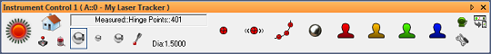
This release has a newly-developed interface for efficient measurement with laser trackers—the Instrument Toolbar.
This new interface is greatly simplified for more streamlined interaction with laser trackers. Less-common detailed settings have been stripped away, leaving just the essential elements of day-to-day measurement,
particularly suited to measurement using the Inspection tab of the SA toolkit. It can be used for single point, stable point, spatial scan, tooling ball, and 4 additional user-defined measurement modes. You will likely find that this new streamlined interface covers a large proportion of your measurement needs, unless finer control is
desired (in which case the traditional tracker interface can be used).
To access this new toolbar, click the Switch to Instrument Toolbar button in the laser tracker interface. For much more on the new tracker instrument toolbar, refer to “Measuring with Laser Trackers” in the What’s New in the SA User Manual.
Instrument Connection Indicator
Connected instruments are now clearly indicated in the graphical view by a new Instrument Connection Indicator, a translucent green ring that hovers around the base of the instrument.
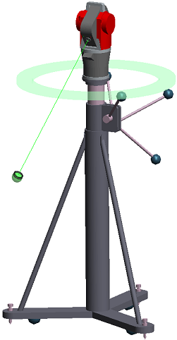
The display and size of this indicator can be controlled in the User Options > Display tab.
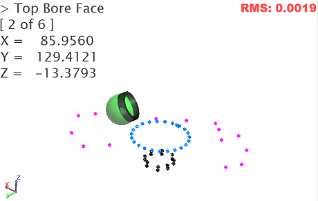
Heads-Up Display
The graphical view is now equipped with a heads-up display (HUD) that includes feature name (if trapping to a feature), number of total points measured (if applicable), target name, measured coordinates, and RMS (if applicable). The HUD’s font, color, transparency, size, and dwell time (how long it persists before clearing from the screen) are all adjustable.
Measurement Count
For measurement trapping (both to relationships and GD&T Datums and Feature Checks) you can now prescribe a specific number of points to be measured for a feature, and measurement trapping will automatically advance to the next feature when all measurements have been received. The current count is also displayed in the HUD.
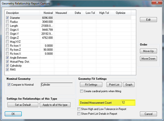
You can also set the default number of points to be used for different feature types on the User Options > Analysis tab. Use 0 to indicate that you do not want a prescribed limit on the number of points.
SA Toolkit Feature Projection Planes
The projection plane options have been improved in the Relationships tab of the SA Toolkit for projection planes.
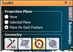
There are now three options:
- None. Does not use a projection plane for the feature.
- Selected Plane. Identical to the “Selected Plane” checkbox of previous versions. You choose a specific plane which will be used as a projection plane.
- Plane for Each Feature. When selected, each additional feature added to the inspection routine will also have a projection plane feature added, so that you first measure the projection plane, then the feature to project to it.
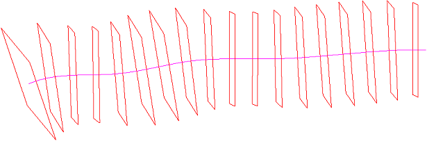
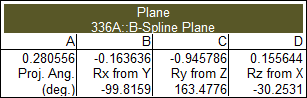
Layout Planes on a Curve
A new command (Construct > Planes > Layout on a Curve Spaced at a Distance) has been added to lay planes along a B-Spline spaced at a specified interval. The planes will be oriented perpendicular to the curve.
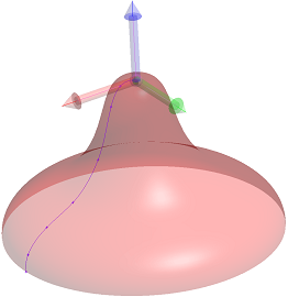
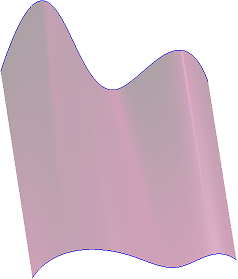
Revolved Surfaces
You can now create a revolved surface by revolving a B-Spline about an object’s axis using Construct > Surfaces > From B-Spline Rotated about an Object. Select the B-Spline, the object, and then choose the axis about which to rotate, and the revolved surface will be created.
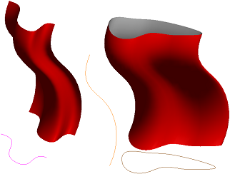
Swept Surfaces
Swept surfaces can now be created using the new Construct > Surfaces > From B-Spline Swept along another B-Spline command. Chose a B-Spline for the profile (can be open or closed), a B-Spline for the sweep path (can be open or closed), and indicate whether the sweep should be performed using pure translation (no rotation) or whether the profile spline should be permitted to rotate through the sweep.
Surfaces From B-Splines or Point Groups
Using Construct > Surfaces > From B-Splines or Construct > Surfaces > From Point Groups, surfaces can now be created from as little as two B-Splines or point groups, where previously four were required.
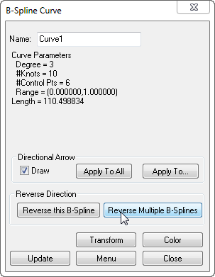
B-Spline Reversal
Multiple B-Splines can now be reversed simultaneously. In a B-Spline’s properties dialog, click the Reverse Multiple B-Splines button.
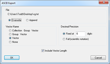
Vector Group Export
Settings for finer control over vector group exporting have been added to the File > Export > Vector Group command.
With these new options, you can:
- Overwrite or append to an existing file
- Specify the vector name format
- Control decimal precision
- Optionally include the length of the vector in the output.
Improved GD&T Surface Datum Handling
In previous versions, general surface features used as datums did not preserve primary/secondary/tertiary relationships. With this improvement, you can now use general surfaces as datums while preserving primary/secondary/tertiary datum priorities.
In order to do this, each general surface datum must be associated with an “offset” line or plane which defines the degrees of freedom that will be locked once the alignment to that datum surface has completed.
This is best explained with an example. Suppose a mostly-horizontal surface with some curvature is desired to be used as a primary datum, and a protruding vertical surface is intended to be the secondary datum. The primary surface can be defined with a horizontal offset plane. This implies that after the data is aligned to the mostly-horizontal surface using all degrees of freedom, the secondary datum is used for alignment with translation along the vertical direction and rotation about the horizontal axes disallowed.
The offset plane or line must be associated with the annotation before the datum is created. Also, a rough alignment using other methods (such as manual positioning, relationship fitting, Quick-Align, etc.) is recommended prior to evaluating general surface checks to maximize surface projection quality.
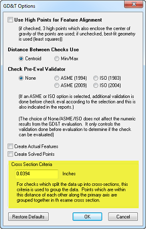
GD&T Cross Section Analysis Control
For GD&T checks which involve analysis of cross-sections, you can now control the distance between points (along the primary axis) used to group points together as a single cross section.
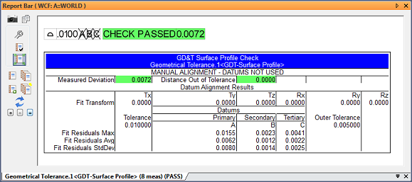
Manual GD&T Alignment
You can now evaluate GD&T feature checks by disabling datum alignment completely—that is, by manually aligning before performing the check.
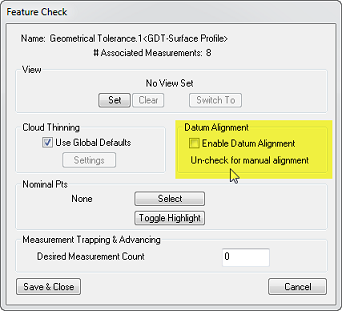
In the feature check’s Properties dialog, disable the Enable Datum Alignment checkbox. Doing so implies that the feature check will be evaluated using the current alignment. Note that this generally will not adhere to the GD&T standard.
When evaluated this way, the feature check has its datums crossed out and the text MANUAL ALIGNMENT - DATUMS NOT USED will appear in the feature check’s summary table in the report bar.
Reporting Improvements
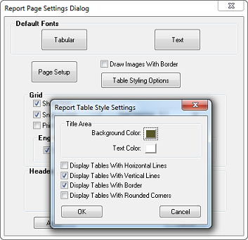
Table Styling
The new Report Table Style Settings dialog—accessible by clicking the Table Styling Options button below—holds the existing table formatting options, and additionally now provides access to control of table header background colors and the text color.
Checkboxes
Checkboxes can now be added to reports.
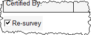
To add a checkbox, right-click the report and select Add New CheckBox.
Repeated Paste
Items can now be pasted multiple times into reports.
Field/Combo Box Excel Support
Fields and combo boxes are now supported for Excel export.
Measurement Plans
Automatic Backups
Automatic backups are now available for the MP Editor. The User Options > Machine Configuration tab has settings for enabling backups and setting the backup interval.
When enabled, the MP Editor will save backups of the script being edited to your backup directory, assuming changes have been made since the last save. Backups are saved to the same location for both embedded and external scripts.
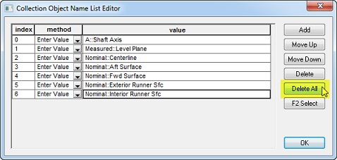
Reference List Editing: Delete All
When editing reference lists, you can now click Delete All to remove all items from the list at one time.
25 New Commands
- Get Instrument Target Status. Returns information on the current instrument target.
- Open XML File. Opens an arbitrary XML file for reading and writing.
- Set XML Attribute. Modifies or creates one or more XML attributes
for a specified node. - Get XML Attribute. Reads one or more attributes from a specified node.
- Close XML File. Closes the XML file.
- Add Item to SA Report at Location. Adds an item to a report with an optional specified page number and position on the page.
- Get Custom Table Cell String. Retrieves a string from a table’s cell.
- Get Custom Table Cell Double. Retrieves a double from a table’s cell.
- Make a String from a String Ref List. Converts a string reference list into a single concatenated string.
- Construct Points at Projection on Surfaces - Parallel to WCF Axis. Creates points by projecting them to a surface along a working coordinate frame axis.
- Construct Points at Projection on Surfaces - Radial from WCF Axis. Projects points radially to a surface from an axis of the working coordinate frame. This essentially creates a cylindrical projection.
- Construct Points at Projection on Surfaces - Spherical from WCF Origin. Projects points spherically outward from the origin of the working coordinate frame’s origin.
- Get Collection Notes. Retrieves the notes for a collection.
- Set Collection Notes. Sets the notes for a collection.
- Get Object Notes. Retrieves the notes for an object.
- Set Object Notes. Sets the notes for an object.
- Get Point Notes. Retrieves the notes for a specific point.
- Set Point Notes. Sets the notes for a specific point.
- Set Relationship Associated Data. Associates data with the specified relationship.
- Get Relationship Associated Data. Retrieves the data associated with the specified relationship.
- Get Vector Group Colorization Options. Retrieves the colorization options for the specified vector group.
- Get Vector Group Display Attributes. Retrieves the display attributes associated with a specified set of colorization options.
- Construct Point Clouds from Existing Cloud Points - Runtime Select. Constructs a point cloud from cloud points selected by the user at runtime.
- Enable/Disable Alignment for Feature Check. Enables or disables GD&T alignment for a given feature check. If disabled, the alignment in place at runtime is used for the feature check evaluation.
- Show/Hide Annotations For Datums. Permits showing or hiding, as well as highlighting, of annotations associated with specified datums.
Click here to view this in pdf format. For additional improvements, fixes, and changes, please see the SA Readme file, accessible through our download page.