What's New in SA
SA Release 2013.08.02
Click here to view this in pdf format.
Expanded File Import/Export Support
The command File>Export>Other>Surface Wireframe Curve File(s) (.crv) has been added. This command writes a wireframe representation of selected surfaces to a text file containing 6 comma-separated values defining two endpoints of a line in Cartesian coordinates: Ax, Ay, Az, Bx, By, Bz.
The command File>Import>Custom Formats>Leica ADF (.adf) has been added to support the import of Leica ADF files.
Direct CAD Access import support has been added for the following file formats:
- ACIS v23 (.SAT, .SAB)
- Autodesk Inventor 2014
- CATIA V5-6R2013 (R23)
- Adobe 3D PDF (.PRC)
- Rhinoceros (.3DM)
- Siemens NX 8.5
Hidden Point Fixtures
In the User Options>Hidden Point-Bar Database tab, you can now define a hidden point fixture. This allows you to use three or more points to define another point on a fixture. Also, hidden points now support target offsets for the computed point.
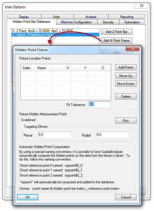
To use this new feature, first measure all points on the fixture and construct the hidden point manually. Then, in the Hidden Point-Bar Database tab, click to add an N Point frame. Add the points defining the fixture’s orientation, then choose to pick the hidden point, and enter offsets for the hidden point if desired.
Remove Measurements By Instrument
The new command Analysis>Measurement Simulations>Remove Measurements By Instrument will remove all measurements associated with a specific instrument, leaving non-measured points behind.
Grid By Distance
In addition to the existing command to lay out points on a grid based on a count (which has been renamed to Construct>Point(s)>Layout>Grid by Count), a new command has been added to lay points out on a grid based on a spacing (Construct>Point(s)>Layout>Grid by Distance).
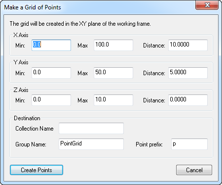
This command maintains the specified spacing, laying off points inside the specified boundary.
New Deletion Commands
Two new commands for deleting relationships and pictures have been added: Edit>Delete>Delete Relationships and Edit>Delete>Delete Pictures. These allow the deletion of one or more relationships or pictures in one command.
Tree Improvements
Several new commands have been added to the context menu in the tree:
- Hide All. Hides everything in the SA job.
- Show All. Shows everything in the SA job.
- Delete Empty Folders. Deletes all empty folders or folders containing only empty folders from the SA job.
- Delete Empty Collections. Deletes all empty collections from the SA job.
To access these new menu items, right-click in an empty area of the tree.
Also, (Working) now appears next to the working coordinate frame in the tree.
Italian Language Support
Italian is now included as a stock language in SA. Stock language translations are now available in the SA Viewer as well.
XML Import
The XML import and export format has been published for the benefit of all users. For more information, refer to “Importing XML Files” in the chapter “Working With Files”.
GD&T: Line Profile Check
A line profile check has been added to GD&T. Line profile checks require objects with directional information (“direction objects”) to be associated with the annotation; these are used to determine how the measurements are grouped into cross-sections. Direction objects can be associated in the annotation properties dialog or when using the GD&T toolbar through an additional prompt during creation.
All measurements within 1 mm of each other in the specified direction are grouped together and analyzed as a cross-section. If multiple direction objects are used, the direction is obtained by averaging the individual object directions.
GD&T Actual Features & Solved Points
The GD&T Options dialog has two new options: Create Actual Features and Create Solved Points.
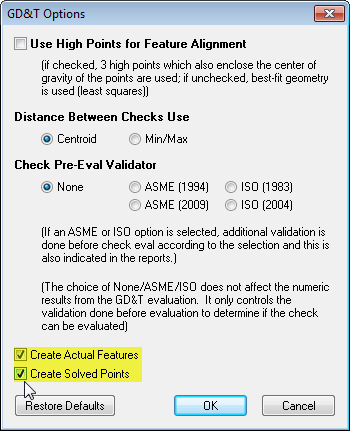
- Create Actual Features. Creates actual measured geometric features for GD&T checks. For instance, if performing a flatness check, the plane representing the orientation of the plane
used for the flatness check is created. This allows you to query your measured points to this plane to determine high and low points, for instance. - Create Solved Points. This creates the center points used for true position analysis when determining if a feature is out of tolerance.
GD&T Actual Diameter Override
For cases in which a single feature check has been applied to multiple cylindrical features , you can you now create size checks for individual features and enable Actual Diameter Override to apply an actual diameter value for that feature without explicitly measuring it.
For instance, in the case of a true position check at MMC, any hole larger in diameter than MMC will result in a bonus tolerance. To apply this bonus tolerance to the true position check without physically measuring the size of the hole, you would create a diameter check for the hole, enable its Actual Diameter Override option, and type in an actual diameter. This will result in a bonus tolerance being calculated and applied, but without requiring you to measure the actual size of the hole.
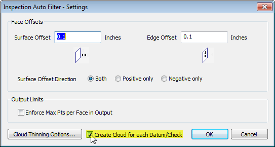
Feature Inspection Auto Filter Cloud Organization
The GD&T>Feature Inspection Auto Filter command has a new Create Cloud for each Datum/Check option which will create a separate point cloud for each datum or feature check. Keep in mind that this may create multiple copies of a given cloud point, since one point may be associated with multiple datums or feature checks.
Reporting Improvements
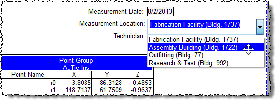
Fields
A new ComboBox widget is now available within reports. Combo boxes allow you to present a drop down list to a user in a report. The list items may be populated from report tags or static text. Simply right-click in the field, select Cell Options>Make ComboBox.
New Tag
A new system tag has been added, <<Filename Short>>, which lists the current filename without the full path.
Borderless Tables
Borderless tables can now be created in reports by right-clicking a cell and selecting Cell Options>Disable All Cell Borders. Select Cell Options>Enable All Cell Borders to re-enable them.
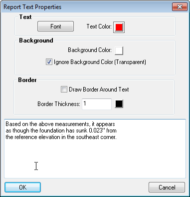
Text Properties
The properties of a text block now contain controls for font, background color, text color, border color, and thickness.
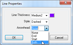
Arrowhead Ends
Line arrowheads can now be added to just the start, just the end, or both ends of a line.
Vector Group TCB Option
The report options for vector groups now has a TCB checkbox which allows disabling the display of the tolerance color box column in its table on a report.
USMN Max Instruments Per Point
The User Options>Reporting tab has a new USMN Max Instruments Per Point option in the Event Reporting box, which controls the maximum number of instruments listed per point within the event details table.
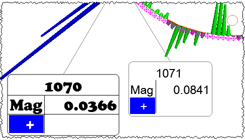
Callout Styling
Individual callouts can now have their own leader/border thickness/color and fonts. To modify an individual callout’s settings, right-click the callout and select Callout Styling.
Callout Snapping
Callouts with leader lines can now be constrained along 45 degree angle increments. Simply hold down the Shift key while dragging a callout with a leader line to snap the callout and its leader line.
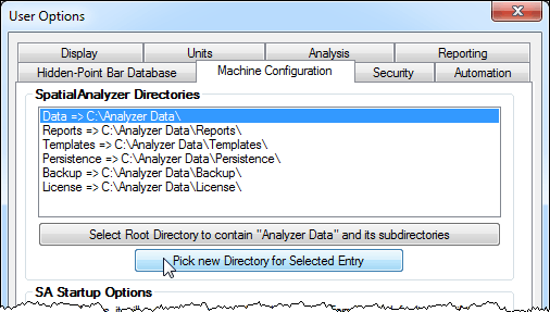
SpatialAnalyzer Directories
The User Options>Machine Configuration tab now allows you to select specific directories for each of the standard SA directories, avoiding the need to edit the registry to make such changes.
Tracker Interface: Remove Simulation Delays
The laser tracker interface has a new option remove simulation delays when connected to a simulated interface. This allows for faster testing when simulated measurements are being performed.
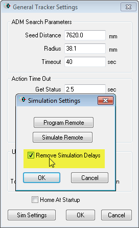
When enabled, the “Point-At” command (e.g. double right-clicking a point in SA) will now simulate a beam lock immediately.
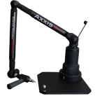
New Interface: API Axxis 7-100 7-DOF Probe Arm
A new interface has been added for the API Axxis 7-100 7-DOF probe arm. This arm runs under the API Baces interface, similar to the 6-100 arm. It supports the new style 7-100 arms with the probe only (no scanner) attached.
New Interface: OmniTrak 2
A new interface has been added for the API OmniTrak 2 laser tracker.
This interface uses the API Device Interface, and has as of yet been untested with hardware.
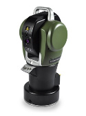
New Interface: Leica AT4xx
This interface has been added to support the Leica AT402. The AT4xx designation is for support of future models. Note that the AT401 can be run via this interface, but the initial AT401 interface and instrument model in SA are preserved for continuity.
New Interface: Assembly Guidance Laser Guide Projector
A new interface has been added for the Assembly Guidance Laser Guide projector.
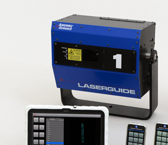
This interface supports creating calibration (registration) files from SA. Simply select Instrument>Laser Projector>Alignment. You will be prompted to select the projector and the group of points you will use to align the projector. In the interface, the UI will be displayed to guide you through driving the projector to each point in sequence with the mouse. Once you have driven to all the points, the projector will register and a file with the registration targets will be created. You may use this file to register the projector with a single click after the one-time manual drive, so long as the projector is not moved.
This interface supports projections from SA or from pre-created files. You are able to project objects from SA by selecting Instrument>Laser Projector>Project Objects. The selected object will be projected and a file will be created using the name of the first object. You have the capability to set the interface to add objects to an existing projection file, or to create a new file with each new projection. This way, you may create your own database of projection files simply by writing them to a common folder on your hard drive.
Once you have created a projection database, you can use the Previous, Current, and Next buttons in the interface to run through a given folder of projection files. You must install LASERGUIDESDK_3_03_11.exe (or later) before running the interface. This may be downloaded from the NRK FTP site: ftp://ftp.kinematics.com/pub/SA/Install/Driver%20Downloads/AssemblyGuidance%20LaserProjector/.
This FTP location also has batch files which need to be executed to register the projector DLL in the SA install.
Automation
SDK Code Generation & Commented Lines
SDK code generation now ignores MP lines which have been commented out.
MP Indentation
Indentation in the MP editor can now be controlled using Tab and Shift+Tab. Select one or more lines, then press these keystrokes to add or remove indentation, respectively.
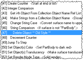
New MP Commands
33(!) new MP commands have been added in this release. They are fully documented in the MP Command Reference, but are briefly listed here for convenience:
- Reverse Plane Normals. Reverses a plane’s normals.
- Get Feature Check Cylinder Eval Options. Retrieves cylinder evaluation options for a cylindrical feature check.
- Set Feature Check Cylinder Eval Options. Sets cylinder evaluation options for a cylindrical feature check.
- Evaluate Feature Checks. Calculates one or more feature checks.
- Start/Stop Feature Check Trapping. Starts or stops trapping to an individual feature check.
- Get GD&T Options. Retrieves the job file’s GD&T options.
- Set GD&T Options. Sets the job file’s GD&T options.
- Start/Stop Relationship Trapping. Starts or stops trapping to a specific relationship.
- Get Number of Pictures in Picture Name Ref List. Obtains the number of pictures in a picture list.
- Get i-th Picture From Picture Name Ref List. Retrieves a specific picture from a picture list.
- Add a Picture to Picture Name Ref List. Adds a picture to a picture list.
- Construct Surface from Point Groups. Fits a surface to points arranged by point group.
- Construct Frame at Robot Link. Creates a frame on a robot’s linkage.
- Make Axis Identifier from String. Converts a string to an “Axis Identifier” for use in a frame construction command.
- Make a Collection Vector Group Name Ref List - Runtime Select. Prompts the user to select one or more vector groups.
- Make a Point Name Ref List - Wildcard Select. Creates a list of points based on a wildcard string.
- Make a Report Ref List - Runtime Select. Makes a list of reports from a user selection.
- Make a Report Ref List from a Collection. Makes a list of all reports in a collection.
- Make a Picture Name Ref List. Creates a list of pictures.
- Make a Picture Name Ref List - Runtime Select. Makes a list of pictures from a user selection.
- Make a Point Name - Ensure Unique. Creates a unique point name guaranteed to not be used in the file.
- Make a Collection Object Name - Ensure Unique. Creates a unique object name guaranteed to not be used in the file.
- Import Nominals from XML File. Imports nominal points from an XML file.
- Merge Measurements into XML File. Merges measured points into an XML file.
- Rename Picture. Renames a picture.
- Cloud Display Control. Sets the size and thinning for cloud points.
- Find Files in Directory. Retrieves a list of files in a given directory.
- Get Directory and Filename from Path. Splits a path into a directory and a filename.
- UDP Send String. Sends a UTF-8 string via UDP over the network.
- UDP Receive String. Receives a UTF-8 string via UDP over the network.
- Ask for User Decision from Image. Displays an image that has clickable regions to get input from the user.
- Get Datum Measurements. Retrieves the points/clouds associated with a specific datum.
- Set Datum Measurements. Sets the points/clouds associated with a specific datum.
Click here to view this in pdf format. For additional improvements, fixes, and changes, please see the SA Readme file, accessible through our download page.